I've never had a 3D printer before, but I've always known that I probably should. So when the new Monoprice Mini Delta 3D Printer was announced on Indiegogo I jumped in and got one of the early shipments for $159. This write-up is partly reminder for me about the steps I took to get it working, and partly to help anyone else just getting started with the Mini Delta. I do all of my work on Linux, so I can't say anything about setting it up under macOS or Windows.


I've printed a few copies of the test object (Maneki-neko) because both of my kids wanted one. I also printed a replacement zipper pull for my daughter's backpack just in time for her to start school. To test out some tiny prints, and further interest my kids, I printed a few simple rings for them (and one for me when I mistook diameter for radius). The most robotics-related thing I've printed is a pulley for some #6 ball chain. I'll be using that to make a simple X-Y pen plotter.
I didn't purchase any filament with the printer, so when it arrived I ran out to Fry's and picked up a 1 kg spool of yellow (my 1 year old was with me and he liked the yellow) Shaxon PLA (1.75mm diameter). I've had no problems with this filament, but have nothing to compare it with.
All in all, I love the Mini Delta. The build volume is not large, but I don't see that as a problem because if I actually tried to fill that volume I'd be printing for most of the day. And all the things I plan on printing are small mechanical components for my projects. For larger structural components I feel like laser cutting is the way to go. I did run into a few hiccups...
Issues encountered
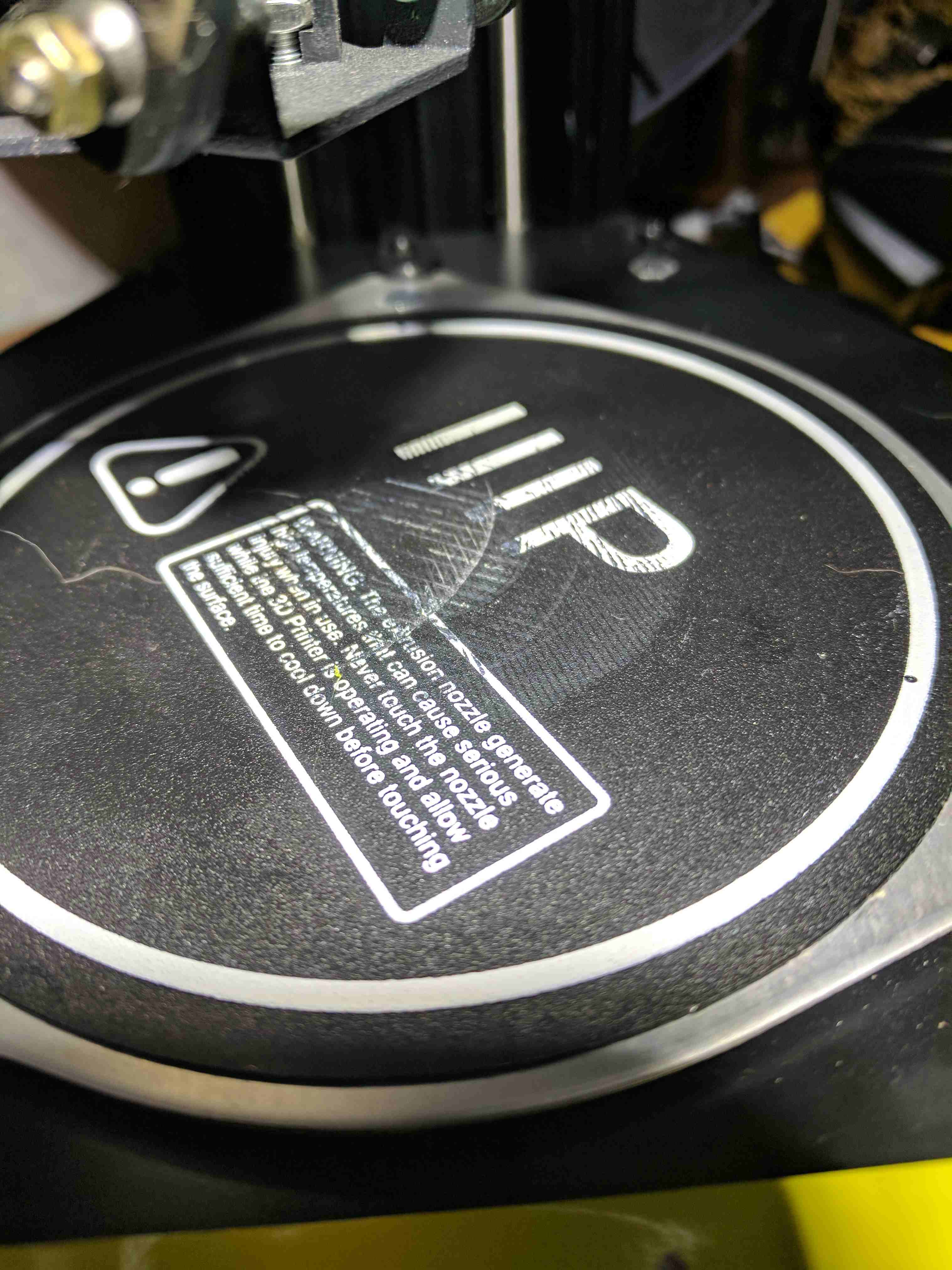
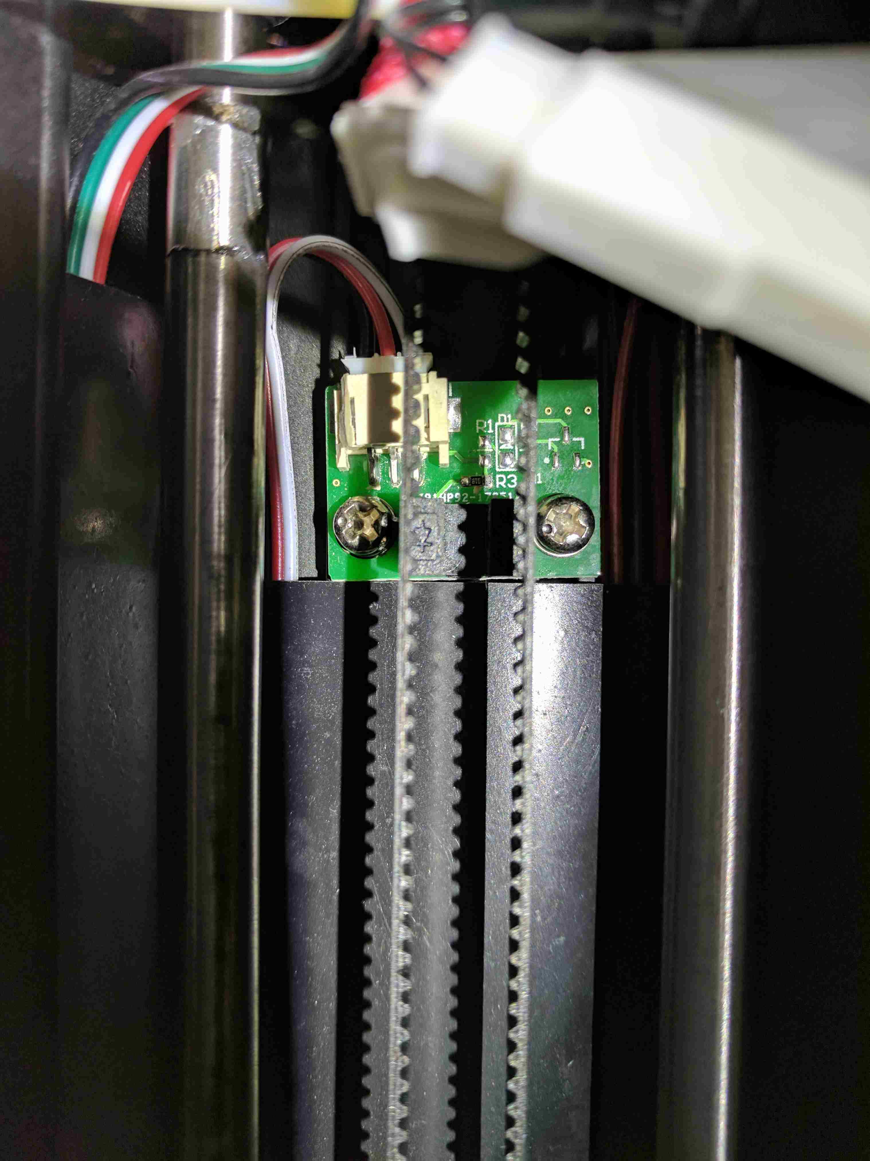
When I first unboxed and plugged in the machine I asked it to home its axes. While trying to home its print head, one of the three timing belt carriages got stuck at the top and made a nasty grinding noise, but managed to move back down, and then seemed fine. I should have investigated more at that time, but wanted to get to printing. So I started the sample print job that came on the SD card. Unfortunately, the sticking at the top of one of the carriages caused the machine to not quite know where the print head was, which made one side of the bed seem lower than it actually was, which caused the print head to scrape the bed while printing the initial raft. The first image below is of the damage to the print bed, pretty minimal actually, and it hasn't affected print adhesion. The second image is a picture of what I think is the culprit: the optical endstop sensor at the top of the column. If you look carefully at the three conductor connector, you can see that the header shroud is not symmetric, in fact the left side has been cut away, manually. I checked and this has been done to all three such connectors at the top of each column. If this manual step had not been done the bearing carriage would hit the header shroud and prevent the carriage from reaching the fully homed position. My guess is that this was a last minute change in parts or placement on the PCB, and this interference wasn't noticed until a few machines were manufactured. And it was likely much cheaper to have someone carve away the offending plastic than to remake the endstop boards. So, my guess is that this endstop header shroud was not fully clearing the carriage, resulting in a bind that caused the stepper controller to lose some steps, resulting in the hot end crash.
The auto bed level sensing is great, though each time it touches down it leaves a small amount of plastic stuck to the bed. I have been removing that between prints, if I didn't I imagine it would throw off the level sensing and cause problems.
While tweaking the tools (described below) to match this machine I generated a few files that directed the print head outside of the workable area, crashing it into parts of the machine that it really shouldn't be touching. I'm amazed that everything seems to be working fine now (I'm sure there's some extra wear on the timing belts and pulleys). I feel like the printer firmware should enforce limits on the print head movement to protect itself.
Tools used
Setting up the printer was not trivial, mainly because I didn't want to use the provided Windows executable. Since I've never had a 3D printer before, I had to decide which tools to use. There are roughly three steps to making something new with a 3D printer:
First you need to design your awesome new object. This is done with a CAD (Computer Aided Design) tool, and the result is a file that describes the geometry of the object. You can also download pre-made objects from sites like Thingiverse. It could be as simple as a file that specifies that it is a cube 1cm on a side. For this I used OpenSCAD.
Second the geometry needs to be turned into a sequence of operations for the printer to use to lay down the plastic needed to make the object. This is called slicing, and is where decisions like how the inside should be filled, how thick each layer should be, and whether some additional support or build platform should be added are made, among many others. The result of this step is almost always a sequence of primitive machine operations called G-code. I used Cura to handle this step.
Finally the G-code needs to be sent to the printer. The Mini Delta has three options here: you can transfer the file with an SD card, you can upload the file using a web interface exposed over WiFi, or you can send the instructions over USB. I used the SD card for the first few prints, tried to get the web interface to work 1, and finally settled on using the USB interface. The USB interface uses one of the standard serial over USB protocols, but you can't just cat the G-code file over the serial port, there is a bit more to it. I found that Octoprint worked well for this.
OpenSCAD
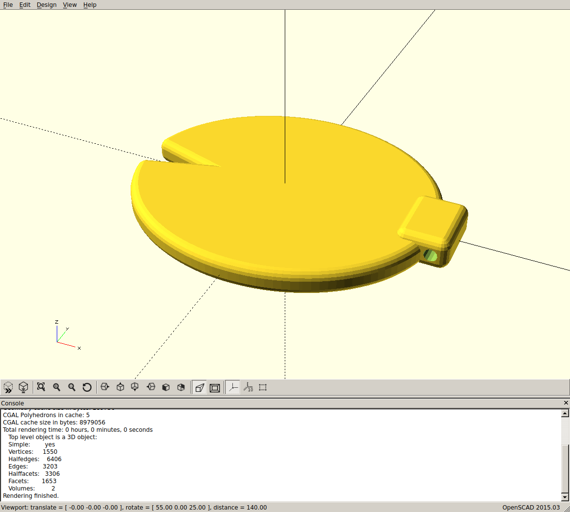
OpenSCAD is not for everyone, it trades constraint based modeling for programmatic control over the model 2. As such it's more of a programmer's tool than a modeling tool. But it is fine for making some objects to print quickly. And I already knew how to use it because it's also what I've used in the past to model objects for laser cutting. Below is a screen shot of the zipper pull rendered in OpenSCAD.
You can find some of the OpenSCAD files I've made on Thingiverse.
Eventually I think I'll be using Solvespace for all my mechanical CAD work. It is a full parametric modeler, which is a very powerful way to create objects.
Cura
I selected Cura mainly because it's what Monoprice shipped on the SD card. First I created a custom printer. This is largely based on the CURA_CONFIG.ini file supplied with the printer on the SD card. But that file is for an older version of Cura that is also supplied on the SD card (as a Windows executable). So some changes had to be made. Unfortunately I wasn't able to find a way of writing a config file and importing it into Cura; I had to enter the printer config manually in the GUI. Below is the resulting configuration file that Cura saves as ~/.local/share/cura/master/definition_changes/Custom+FDM+printer_settings.inst.cfg.
[general]
version = 2
name = Custom FDM printer_settings
definition = custom

[metadata]
type = definition_changes
setting_version = 1

[values]
gantry_height = 0
machine_center_is_zero = True
machine_depth = 120
machine_end_gcode = ;End GCode
        M104 S0                      ;extruder heater off
        M140 S0                      ;heated bed heater off (if you have it)
        G91                          ;relative positioning
        G1 E-1 F300                  ;retract the filament a bit before lifting the nozzle, to release some of the pressure
        G1 Z+0.5 E-5 X-20 Y-20 F4800 ;move Z up a bit and retract filament even more
        G28 X0 Y0                    ;move X/Y to min endstops, so the head is out of the way
        M84                          ;steppers off
        G90                          ;absolute positioning
machine_head_with_fans_polygon = [[0, 0], [0, 0], [0, 0], [0, 0]]
machine_heated_bed = True
machine_height = 120
machine_shape = elliptic
machine_start_gcode = ;Sliced at: {day} {date} {time}
        ;Basic settings: Layer height: {layer_height} Walls: {wall_thickness} Fill: {infill_sparse_density}
        ;Print time: {print_time}
        ;Filament used: {filament_amount}m {filament_weight}g
        ;Filament cost: {filament_cost}

        G21            ;metric values
        G90            ;absolute positioning
        M82            ;set extruder to absolute mode
        M107           ;start with the fan off
        G28            ;Home
        G29 C-0.8 Z0.3 ;Auto level print platform
        G1 Z15.0 F4800 ;move the platform down 15mm
        G92 E0         ;zero the extruded length
        G1 F200 E3     ;extrude 3mm of feed stock
        G92 E0         ;zero the extruded length again
        G1 F4800

machine_width = 120
material_diameter = 1.75
Then I created a custom profile based on the draft profile and set the build plate adhesion type to "Raft", with an extra margin of 5mm. I found that without the raft it was extremely difficult to remove the prints. The raft also seems to protect the build plate a bit (the printing on the build plate sticks to the bottom of the print a bit). This results in a configuration file saved as ~/.local/share/cura/master/quality/custom_draft+quality+pla.inst.cfg. Cura does provide an export/import option for profiles, but it generates a ZIP file with a bunch of dummy profiles for up to eight extruders, not a simple text description like I was expecting. It seems easier to handle this step in the GUI as well.
[general]
version = 2
name = Draft Quality PLA
definition = fdmprinter

[metadata]
type = quality_changes
quality_type = draft
setting_version = 1

[values]
adhesion_type = raft
raft_margin = 5
Fortunately it is possible to easily import a filament description. Below is the material description file that I created for Cura.
<?xml version='1.0' encoding='utf-8'?>
<fdmmaterial version="1.3" xmlns="http://www.ultimaker.com/material">
  <metadata>
    <name>
      <brand>Shaxon</brand>
      <material>PLA</material>
      <color>Yellow</color>
      <label>yellow</label>
    </name>
    <setting_version>1</setting_version>
    <GUID>ea2fff89-1826-406f-bab0-4e612f2e5e20</GUID>
    <version>1</version>
    <color_code>#f4f442</color_code>
    <description></description>
    <adhesion_info></adhesion_info>
    <compatible>True</compatible>
  </metadata>
  <properties>
    <density>1.25</density>
    <diameter>1.75</diameter>
  </properties>
  <settings>
    <setting key="print temperature">190.0</setting>
    <setting key="heated bed temperature">70.0</setting>
    <setting key="retraction amount">4.0</setting>
    <setting key="retraction speed">80.0</setting>
    <setting key="standby temperature">150.0</setting>
    <setting key="print cooling">100.0</setting>
  </settings>
</fdmmaterial>
USB connection
The generic Linux usb serial driver doesn't yet know about the USB VID:PID pair for this printer, so in order to connect you need to provide it with them. My solution was to create a simple pair of UDEV rules.
#
# Add USB VID/PID for Monopride Mini Delta
#
ACTION=="add", SUBSYSTEM=="usb", ATTR{idVendor}=="cfce", ATTR{idProduct}=="0300", RUN+="/usr/bin/modprobe usbserial", RUN+="/bin/sh -c 'echo $attr{idVendor} $attr{idProduct} > /sys/bus/usb-serial/drivers/generic/new_id'"

#
# Construct a symlink to the TTY generated for the printer.
#
SUBSYSTEM=="tty", ATTRS{idVendor}=="cfce", ATTRS{idProduct}=="0300", SYMLINK+="monoprice_mini_delta"
I saved this as /etc/udev/rules.d/51-monoprice-mini-delta.rules, reloaded UDEV's rule database with sudo udevadm control --reload, and finally unplugged and plugged back in the printer USB cable. That gave me a handy symlink (/dev/monoprice_mini_delta) to use. To test that it worked I used screen to open the serial device (screen /dev/monoprice_mini_delta 115200) and sent a few G-code commands to the printer. In particular I sent G28 to home the axes, and M115 to get the machine information. For me M115 returns:
NAME. Malyan
VER: 3.7
MODEL: M300
HW: HG01
BUILD: Jun 26 2017 19:04:37
If you've never used screen, you can exit with Ctrl-A followed by '\'.
Octoprint
Setting up Octoprint on Arch Linux (my preferred desktop distribution) is pretty easy if you're familiar with the AUR. The package to install is octoprint-venv. And once installed you can enable and start the service with:
sudo systemctl enable octoprint.service
sudo systemctl start octoprint.service
Be warned: this runs Octoprint as root, probably not the best decision security-wise. By default Octoprint will start a web server listening to just the local machine on port 5000. So navigate over to http://localhost:5000 and you should be greeted with a nice GUI. The first thing to do is to connect to the printer. Use /dev/monoprice_mini_delta for the serial port, and 115200 for the baud rate. Once connected, go to the Control tab and try something safe, like turning the fan on and off.
The Octoprint GUI is pretty self-explanatory at this point; you can upload G-code files and print them. You also have a number of options for monitoring the print job, including graphs of bed and extruder temperature, visualization of the G-code instructions sent to the printer, and a raw stream of instructions.
The Control tab is also a lot of fun, but be careful, the Mini Delta's firmware doesn't prevent you from running the print head into the edge of the frame or down into the print bed. So make small moves until you have a good understanding of the machine.
I managed to get the WiFi working easily enough, but was not able to upload a file using the web UI. I didn't spend much time debugging that as I switched to using OctoPrint over USB and that has been rock solid. OctoPrint's UI is also much more polished.
[return]This may be a false dichotomy, but I haven't seen a CAD programming language that allows for the creation of constraints. A constraint based CAD language would be interesting to work in.
[return]